


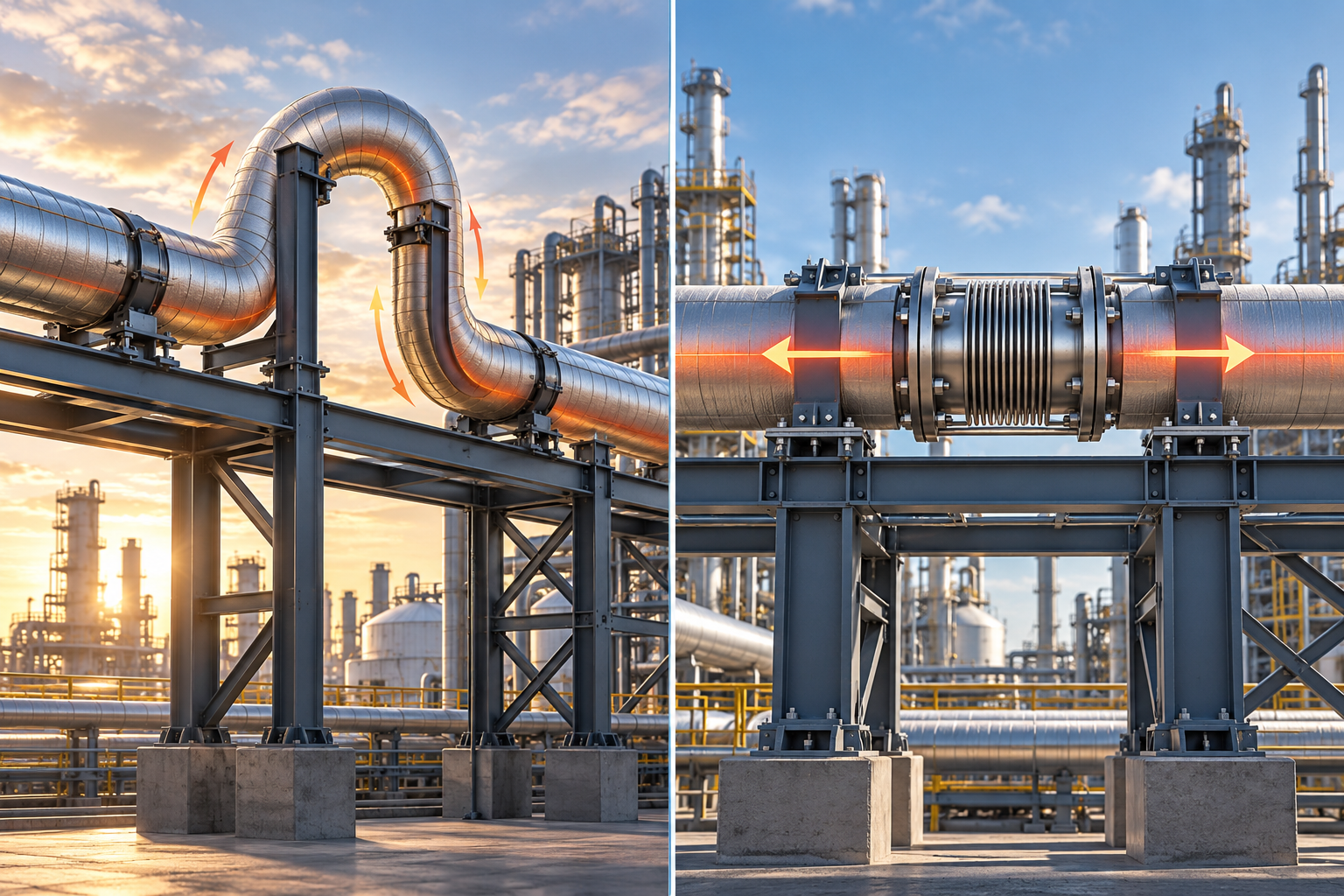
Expansion loops: using the flexibility of the pipe
With natural expansion compensation, pipe bends and sufficiently long pipe legs absorb the thermal movements by elastic deformation. Besides a purpose-built U-shaped expansion loop, existing L- or Z-shaped pipe runs can therefore also be suitable. The prerequisite is that the resulting stresses and connection loads are kept under control.
For design this means: before an expansion joint is specified, it is worth examining the pipe routing. Not every long or hot line automatically needs a bellows expansion joint.
In a pipe that is continuously connected so as to transmit tension, the pressure force path through the pipe wall is maintained. An expansion loop does not interrupt this force path in the way an unrestrained axial expansion joint does. The additional bellows pressure force, which would otherwise have to be resisted by appropriately designed anchors, therefore does not arise. That does not mean, however, that the pipe or its supports are free of forces altogether.
On pipe racks in particular this difference matters: the pressure thrust of an axial expansion joint acts along its axis – with a horizontal arrangement, therefore, horizontally. With large effective bellows cross-sections and high pressures this can result in a governing load on the structural steelwork.
An expansion loop avoids this particular load from an unrestrained bellows. Thermal spring forces, weight loads and the other actions must nevertheless be taken into account.
For modifications to existing plant, the investigation should therefore not begin with the question “Where can another expansion joint be fitted?” but with “Which possibilities for movement does the existing plant offer?”
Our design approach at ENTRACON is to examine alternative pipe routes and support concepts together. This includes, for example, making use of existing changes of direction, sufficiently long connecting legs or a different arrangement of guides and anchors. A pipe stress analysis serves as the basis for comparing the variants.
The aim is not to avoid an expansion joint as a matter of principle. The aim is a solution in which movements, pipe stresses, support loads and nozzle loads fit together.
A newly arranged expansion loop needs space for the pipe run and its movement. Additional pipe length and bends also mean more material, welded joints, insulation and possibly further supporting structures. Added to this is additional flow resistance. These consequences have to be assessed as part of the comparison of variants.
The process side must not be neglected either: on steam lines, unfavourably arranged loops can encourage condensate to collect. Slope and drainage must therefore suit the chosen geometry.
An expansion loop is thus not a better solution across the board – but a variant that should be examined before an additional flexible component is used.